
 русский
 简体中文
简体中文

A valve in service rarely stays at one temperature. The process warms up and cools down. The ambient temperature changes with the seasons. Steam tracing turns on and off. Each temperature change causes the metal parts of the valve to expand or contract. The seat seals move. The stem packing shifts. The bolted flanges experience changing loads.
Thermal cycling becomes more challenging when the valve stays closed for long periods. Liquid trapped inside the valve body heats up. As the temperature rises, the liquid expands. Pressure builds inside the cavity. Without a pressure relief path, the pressure can approach the design limits of the valve. The seats, stem seals, and body joints all experience stress that they would not face under steady temperature conditions.
The risk of leakage increases with each thermal cycle. A seal that holds at room temperature may open a small gap when the parts expand differently. A seat that seals under steady pressure may lose contact when the temperature drops. Repeated cycles can cause fatigue in the sealing materials and the metal components.
The floating ball design works on a simple principle. The ball is not held in a fixed position. Instead, it floats between the upstream and downstream seats. The line pressure pushes the ball against the downstream seat. That pressure creates the seal.
When the temperature changes, the ball and the seats expand at different rates. The seat materials typically have a higher coefficient of thermal expansion than the metal ball and body. The seats may squeeze against the ball more tightly as temperature rises, or they may loosen as temperature drops. The shifting seal loads affect the leakage rate.
The sealing mechanism of a floating ball valve is also a potential weakness under thermal cycling. The ball moves with the pressure, which helps maintain the seal under changing conditions. But the movement also causes wear. Each thermal cycle can cause the seats to rub against the ball surface. The rubbing gradually wears the seat material, increasing the leak rate over time.
Relief-slot seats address a specific problem in thermal cycling. Liquid trapped in the valve body expands when heated and creates pressure. Without a relief path, this pressure loads the seats, increasing wear and making operation difficult. A relief slot in the seat allows the trapped fluid to vent into the pipeline, reducing the pressure buildup.
| Seat Material | Temperature Range | Self-Relief Feature | Thermal Cycling Suitability |
|---|---|---|---|
| PTFE | -46°C to 232°C | Optional | Good for moderate ranges |
| RPTFE | -46°C to 232°C | Optional | Better creep resistance |
| PEEK | -46°C to 260°C+ | Optional | Good for higher temperatures |
| UHMWPE | -46°C to 93°C | Optional | Limited to lower temperatures |
| Metal-seated | Up to 500°C+ | Not needed | Excellent for high temperatures |
Live-loaded packing systems compensate for the expansion and contraction that occurs during thermal cycling. A Belleville washer stack applies constant load to the packing gland. As the temperature changes and the packing expands or shrinks, the spring load adjusts. The packing stays under compression and maintains the seal.
Graphite packing handles high temperatures better than PTFE-based packing. The material withstands temperatures that would cause PTFE to soften and extrude. Graphite packing also offers fire-safe performance, maintaining a seal even after a fire exposure. The trade-off is higher operating torque.
Independent packing glands allow adjustments without disassembling the actuator. The packing can be tightened as it wears or settles, without disturbing the valve position or the actuator mounting. The feature reduces the need for full valve disassembly during maintenance.
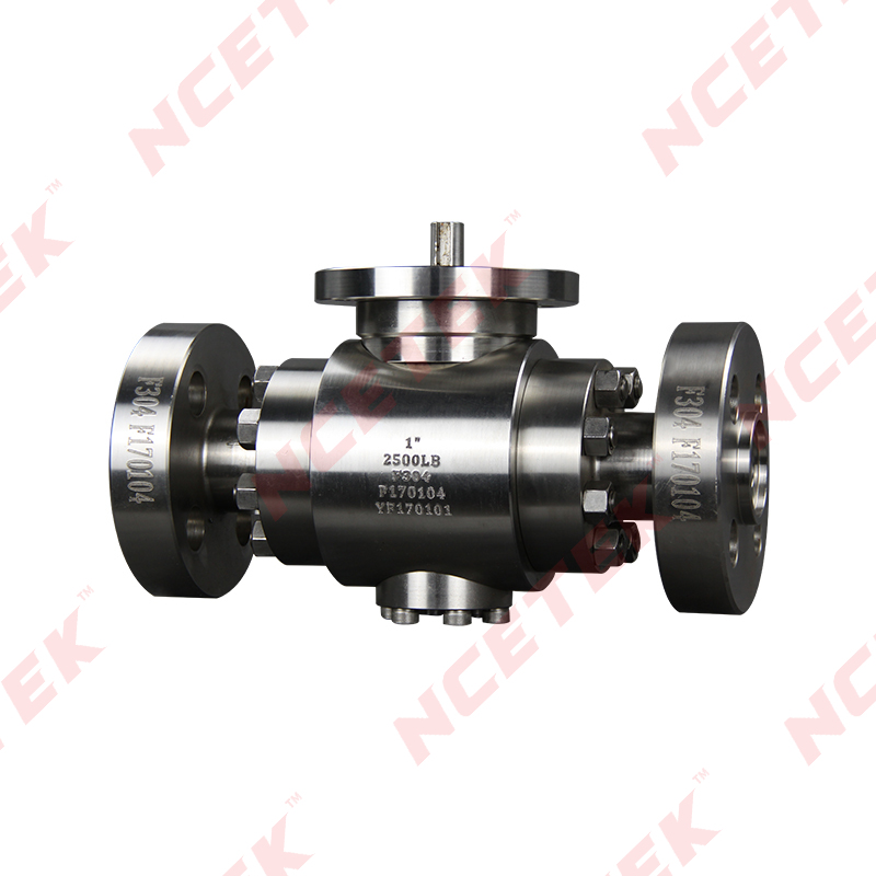
The body of a Flanged Floating Ball Valve typically comes in a one-piece or two-piece design. A one-piece body has fewer potential leak paths than a multi-piece construction. The fewer joints, the fewer places where thermal cycling can cause a leak.
Flanged connections present another area of concern under thermal cycling. The bolts holding the flanges together see changing loads as temperature rises and falls. A flange that was torqued correctly at ambient temperature may see a different bolt load at operating temperature. The gasket between the flanges must accommodate these load changes without relaxing its seal.
The body design also affects how the valve handles the thermal expansion of internal components. The ball and the seats expand at different rates. A body with sufficient clearance for the internal parts prevents binding that would occur if everything expanded into a tight fit.
Valve manufacturers provide temperature ratings for their products. A Flanged Floating Ball Valve with resilient seats typically operates from -46°C to 232°C. The rating covers the range where PTFE and similar materials maintain their sealing properties.
Extending the temperature range requires different materials. PEEK seats push the upper limit to around 260°C. Metal-seated designs reach 500°C and higher. Each step up in temperature requires changes to the seat material, the packing, and sometimes the body material.
The pressure rating also changes with temperature. A valve rated for a certain pressure at room temperature has a lower rating at elevated temperature. The relationship between temperature and pressure appears in the valve's pressure-temperature chart. That chart provides the information needed to select a valve for a specific application.
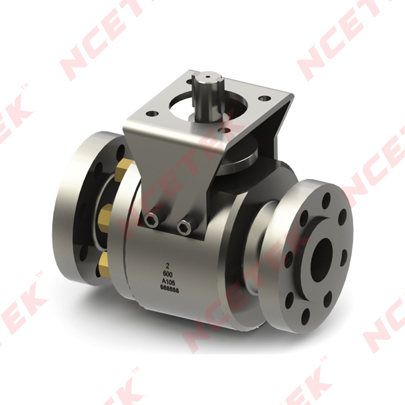
Manufacturers test valves to verify their performance under thermal cycling. The tests expose the valve to repeated temperature cycles while measuring leakage. The number of cycles and the temperature range depend on the expected service conditions.
High-temperature cycling tests for metal-seated ball valves often run at 550°C and 650°C. The tests simulate the conditions found in high-temperature processes like steam generation or chemical processing. A valve that passes these tests demonstrates its ability to maintain sealing through repeated thermal cycles.
The results of thermal cycle testing show a pattern. The seat leakage may increase slightly with each cycle as the seating surfaces wear. The rate of increase depends on the materials and the temperature range. Valves with resilient seats typically show more wear at higher temperatures, while metal-seated valves wear more slowly.
Trunnion-mounted ball valves take a different approach to thermal cycling. The ball is fixed in position by bearings at the top and bottom. The seats move toward the ball, rather than the ball moving toward the seats. The design reduces the effect of thermal expansion on the seat loading.
The floating design relies on the ball moving between the seats. The movement creates a wiping action that can scrape the seat surface. Over many thermal cycles, the scraping can wear the seat material and increase leakage. Trunnion-mounted designs do not have the same wiping action because the ball stays in place.
The comparison between the two designs shows that each has advantages. A Flanged Floating Ball Valve suits applications with moderate temperature ranges and where the cost difference matters. Trunnion-mounted valves handle higher pressures and more severe thermal cycling but come at a higher cost.
Selecting the correct seat material for the expected temperature range is the first step. A valve with PTFE seats in a 300°C process will not last. A valve with PEEK or metal seats in the same process has a chance of meeting the requirements.
Stem packing inspection should be part of the regular maintenance routine. Packing that has settled or extruded can be tightened or replaced. The packing gland should maintain a seal without excessive tightening that would increase operating torque.
Monitoring for signs of thermal fatigue in flanges and body joints helps prevent leaks. A flange that has leaked and been retorqued multiple times may need new gaskets. A body joint that shows signs of movement should be inspected for damage.
Working with a Floating Ball Valve Manufacturer early in the design process provides access to application-specific guidance. The manufacturer can recommend materials and designs based on the temperature range and the expected number of thermal cycles. A valve selected with the help of the manufacturer is more likely to perform reliably over its service life.
 nce@cnnsv.com
 +86-15727968392 / +86-15397375798
 +86-577-67091815
 +86-577-67091815
 Dongou Industrial Zone, Oubei Street, Yongjia County, Wenzhou City, Zhejiang Province, China


Contact Us