
 русский
 简体中文
简体中文

Inside the body of a floating ball valve lies a space that does not exist in many other valve types. When the valve closes, the ball presses against the downstream seat, creating a seal on both sides. The ball itself, along with the two seats, forms a closed chamber around the ball. This chamber, known as the cavity, sits between the upstream and downstream sealing points.
The floating design contributes directly to how this cavity forms. The ball moves slightly in the flow direction when pressure is applied, seating itself firmly against the downstream side. The upstream seat also contacts the ball, completing the enclosure. The result is a fixed‑volume space that contains whatever fluid was present when the valve closed.
This cavity becomes isolated from the main pipeline flow. Fluid inside cannot move back upstream past the upstream seat. It cannot move downstream past the downstream seat. Whatever enters that space during operation remains there unless some path for relief exists. The size of the cavity varies depending on valve size and design, but every floating ball valve has one.
A liquid trapped in a closed cavity behaves in ways that seem counterintuitive at first. Unlike gases, which compress easily, liquids resist changes in volume. When a liquid completely fills a fixed space and temperature increases, the liquid expands but the space does not. The pressure rises dramatically from that small thermal expansion.
Fluid compressibility plays a central role in determining how much pressure builds. Liquids have very low compressibility, meaning they do not reduce volume much even under high pressure. When a trapped liquid warms, its volume wants to increase, but the cavity walls prevent expansion. The pressure rises sharply until something gives—the seats, the body, or the fluid itself.
The pressure that develops can far exceed the normal operating pressure of the valve. What began as a modest line pressure may multiply many times inside the cavity simply from a moderate temperature increase. The mechanism requires no external pump, no pressure source, and no operator action. It occurs purely from the combination of trapped liquid and changing temperature.
Temperature change stands as the most common driver of cavity pressure buildup. Process temperatures fluctuate, ambient conditions change, and valves may experience solar radiation when installed outdoors. Each of these sources can introduce temperature changes that affect the trapped media.
Thermal expansion in liquid services follows a straightforward relationship. As temperature rises, the liquid expands. The cavity volume stays constant. The pressure must increase to accommodate the volume mismatch. Even a small temperature rise can produce a large pressure rise because of the low compressibility of liquids.
Cryogenic fluids present a special case. Liquefied gases stored at very low temperatures absorb heat from the environment. That heat input changes the fluid state. The pressure rise from thermal expansion alone does not capture the full effect, because the fluid behavior also includes changes in vapor pressure and potentially phase state.
Ambient temperature cycles add another layer of complexity. A valve closed during the cool morning may experience a temperature rise as the day warms. That temperature change begins the pressure build process. By the time the valve needs to open, the cavity pressure may have reached levels that make operation difficult.
Phase change introduces a different mechanism for pressure development. When trapped liquid changes to vapor, the volume occupied by that material increases enormously. In a fixed cavity, that volume increase translates directly into pressure.
The specific risks with liquefied gases in cryogenic service deserve attention. Liquefied natural gas, for example, remains liquid at very low temperatures and under pressure. If trapped in a valve cavity and warmed above its boiling point, the liquid vaporizes. The resulting gas occupies many times the volume of the original liquid. The fixed cavity cannot accommodate that volume, so pressure rises until the vapor compresses or the system yields.
This mechanism differs from simple thermal expansion in two important respects. The volume change from phase transition is far greater than thermal expansion. The pressure rise can occur even with minimal temperature change, as long as the temperature crosses the vaporization threshold. Phase change can produce more sudden and more extreme pressure events than thermal expansion alone.
Seat leakage provides another path for pressure to enter the cavity. The upstream seat may allow small amounts of line fluid past its sealing surface during operation. The pressure in the cavity then approaches the upstream pressure. Once the cavity reaches line pressure, flow across the seat stops.
The downstream seat, by contrast, often holds tight. If the downstream seal does not leak, the pressure in the cavity cannot escape. The pressure remains locked inside, trapped behind a seat that does not allow reverse flow.
Over multiple operating cycles, pressure accumulation can occur. Each time the valve opens and closes, small amounts of fluid may pass the upstream seat into the cavity. The downstream seat releases none of it. The cavity pressure gradually approaches the highest pressure encountered during operation.
| Condition | Effect on Cavity Pressure |
|---|---|
| Upstream seat leaks, downstream seat seals | Pressure enters cavity and remains trapped |
| Upstream seat holds, downstream seat leaks | Pressure may relieve to downstream side |
| Both seats hold | No flow into or out of cavity; pressure from trapped media only |
| Both seats leak | Pressure equalizes with line; trapped media less isolated |
| Differential thermal expansion | Seating forces may change, affecting leakage rates |
Ball geometry influences how pressure communicates between the cavity and the pipeline. Some designs incorporate features that allow pressure equalization. Others provide no such path.
A solid ball without any opening presents a complete barrier. Pressure that enters the cavity has no way to escape except through the seats. If both seats seal effectively, the pressure remains trapped indefinitely. This arrangement works well for many applications but carries the cavity pressure risk discussed earlier.
A vented ball includes a small hole drilled through the ball. This equalization hole connects the cavity to the upstream side of the valve. When the valve is closed, the hole provides a path for cavity pressure to bleed back upstream. The upstream side may see a slight pressure increase, but the cavity does not trap extreme pressure.
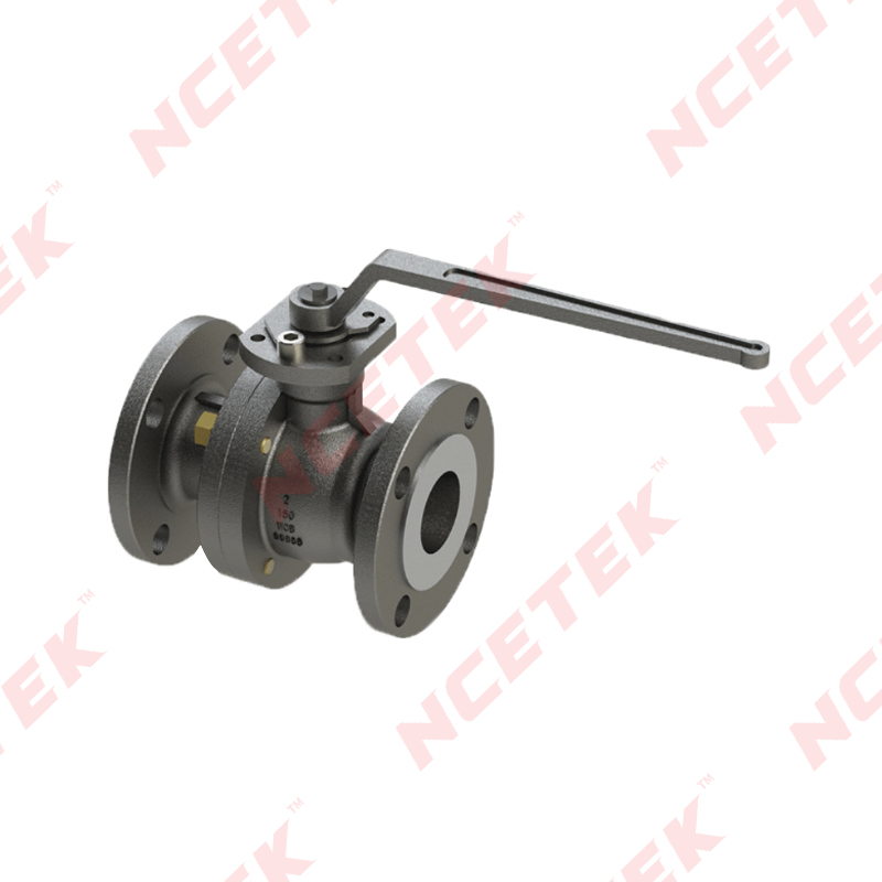
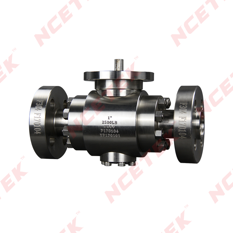
The directionality of vented ball designs deserves attention. A hole that vents upstream works only when the valve is installed in a specific orientation. If installed backward, the vent may not function as intended. Some Flanged Floating Ball Valve designs include vents, while others rely on different pressure management strategies.
The following design approaches affect how pressure gets managed:
Seat design offers another approach to cavity pressure management. Self‑relieving seats incorporate features that allow pressure to bleed past the seat under specific conditions. The seat does not simply leak—it opens a controlled path when cavity pressure exceeds line pressure by a certain margin.
The principle depends on seat movement. The seat material, or the spring behind it, allows the seat to shift slightly away from the ball when cavity pressure pushes from behind. That slight movement creates a gap through which pressure can escape. Once the cavity pressure drops to an acceptable level, the seat returns to its sealing position.
The conditions under which self‑relieving occurs vary by design. Some seats relieve at a fixed differential. Others relieve based on seat geometry and material properties. The design must balance effective sealing under normal conditions with reliable relief when overpressure occurs.
Self‑relieving seats require careful material and geometry selection. Too much movement and the seat may not seal effectively. Too little movement and the relief function may not activate. The performance of self‑relieving seats represents a key consideration for any Floating Ball Valve Manufacturer developing products for critical services.
Cavity fillers reduce the available volume inside the valve body. Less volume means less fluid can become trapped. The pressure that develops from thermal expansion or phase change relates to the amount of trapped fluid. Reducing that amount reduces the potential pressure.
Fillers made from materials like PTFE or other soft inserts occupy space that would otherwise contain process fluid. They do not absorb the fluid—they simply take up volume so less fluid enters the cavity in the first place. The filler material sits around the ball, leaving room for ball movement while minimizing empty space.
Applications with stagnant or crystallizing services often benefit from cavity fillers. In these services, fluid that remains trapped may not only cause pressure problems but also solidify or deposit solids. Fillers help prevent buildup and reduce the volume of material that could cause issues.
Material selection for fillers requires attention to service conditions. The filler must withstand the same pressures and temperatures as the valve. It must not degrade, swell, or leach into the process. The compatibility of filler material with the specific fluid and operating conditions requires verification.
Operators may notice several signs that cavity pressure has developed. Changes in valve operating torque provide one indicator. A valve that turns harder than normal may have cavity pressure pushing against the ball. The increased resistance comes from the pressure differential across the ball and seats.
During manual operation, high cavity pressure can make the valve feel stiff. The operator must overcome the force created by trapped pressure. In severe cases, the valve may refuse to move or require extraordinary effort to operate. The change in operating feel from one cycle to the next may signal cavity pressure issues.
Downstream sealing can also be affected. High cavity pressure may push the upstream seat against the ball, altering the sealing forces. The downstream seat may experience additional loading. These changes can affect how well the valve seals when open or when transitioning between positions.
Observable signs that may indicate cavity pressure:
The condition may not be externally visible until the valve is operated. No external gauge exists on most valves to indicate cavity pressure. Operators may not know pressure has built up until they attempt to move the valve.
Understanding cavity pressure mechanisms allows manufacturers to design products that perform reliably in actual service. The application conditions for each valve dictate what design features are appropriate. A valve for high‑temperature liquid service may need different pressure management than one for cryogenic gas.
Matching valve design to service conditions requires knowledge of how cavity pressure develops. A Flanged Floating Ball Valve intended for thermal cycling service should incorporate features that address expansion and contraction. A valve for liquefied gas service must account for potential phase change. The application knowledge of a Floating Ball Valve Manufacturer shapes how well their products suit the intended use.
Design choices directly influence field performance and reliability. A valve with appropriate pressure management features will operate smoothly and seal effectively throughout its service life. A valve lacking these features may develop operational issues that lead to maintenance or replacement.
The relationship between understanding cavity pressure and delivering suitable products matters for long‑term customer satisfaction. Operators appreciate valves that work as expected without unexpected problems. Manufacturers who understand the mechanisms behind cavity pressure and design accordingly build products that earn lasting trust in the field.
 nce@cnnsv.com
 +86-15727968392 / +86-15397375798
 +86-577-67091815
 +86-577-67091815
 Dongou Industrial Zone, Oubei Street, Yongjia County, Wenzhou City, Zhejiang Province, China


Contact Us