
 русский
 简体中文
简体中文

A pipeline is only as manageable as the valves placed along it. Isolation points allow sections to be taken out of service, flow to be directed or stopped, and maintenance work to proceed without draining an entire network. Ball valves serve this role across many parts of a pipeline system, from main transmission lines to branch connections and terminal points.
Two construction approaches dominate in this category: side entry and top entry. Both use a rotating ball with a bore that aligns with the flow path when open and blocks it when closed. Both operate with a quarter turn. The difference lies in how the valve is assembled and, more importantly for pipeline operators, how it can be serviced once installed.
The question worth working through is how top entry design supports maintenance work, and where side entry construction follows a different logic. The answer shapes decisions about installation, access planning, and long‑term operating cost.
Before separating the two configurations, it helps to see what they have in common.
At the center of both sits a ball with a through‑bore. When the bore aligns with the pipeline, flow passes. When the ball rotates a quarter turn, the bore faces the body wall and flow stops. Seats on either side of the ball contact its surface to form a seal. A stem connects the ball to an external handle or actuator, passing through the body or bonnet depending on construction.
Pressure containment is a shared requirement. Whether the body is built in one piece or several, it must hold line pressure without leakage at joints, seals, and the stem passage. Material selection, wall thickness, and sealing design all serve that requirement in both configurations.
The distinction between side entry and top entry is not about function. It is about how the internal components are placed into the body and how they can be reached later. That difference carries practical consequences for installation, service access, and the conditions where each design fits.
A side entry valve is assembled from multiple body sections joined along a vertical plane. The ball, seats, and stem are loaded into one section before the pieces are brought together and secured with bolts or threaded connections.
The assembly sequence shapes the service sequence. To reach the ball or seats after installation, the body sections must be separated. That typically means removing the valve from the line, since the joints run through the middle of the body and cannot be opened while the valve remains bolted between flanges or welded into position.
This construction has practical advantages. The body can be built in standard sections that suit a range of sizes, and the assembly process is well established. For pipelines where valves are accessible and can be taken out of service without disrupting other work, side entry design covers the requirement.
The trade‑off appears when access is difficult or downtime is costly. A valve welded into a line or positioned in a confined space cannot be easily separated. In those situations, the service path matters as much as the valve's function.
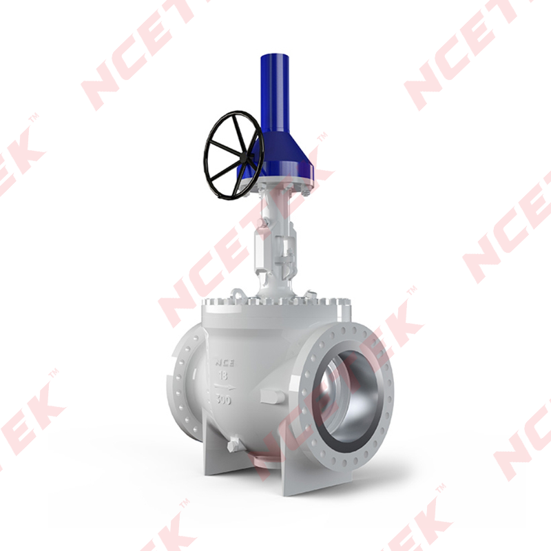
A top entry valve takes a different approach. The body is a single piece with an opening at the top. Internal components — ball, seats, and stem assembly — are inserted through that opening rather than between body sections. A bonnet or cover is then secured over the opening to contain pressure.
The stem passes through the bonnet rather than through the body wall. This arrangement means the pressure boundary at the top is a single flanged or bolted joint, separate from the body itself. The body has no vertical split, so there is no joint running through the middle of the pressure‑containing shell.
Assembly follows a straightforward sequence: components lowered into the body from above, bonnet placed and tightened, stem connected to the ball, and the assembly tested. Because the body is one piece, the number of potential leak paths through the shell is reduced compared with a multi‑piece design.
The significance of this construction shows up during service. Reaching the ball or seats requires removing the bonnet, not separating the body. The valve can remain in the line, connected at both ends, while its internal parts are accessed from above. That capability changes how maintenance is planned and how long a service interruption lasts.
| Aspect | Side Entry | Top Entry |
|---|---|---|
| Body construction | Multiple sections joined vertically | Single piece with top opening |
| Internal access | Body sections separated | Bonnet removed from above |
| Service in line | Typically requires removal | Possible without removing from line |
| Leak paths through shell | Joints along body split | Fewer body joints |
| Clearance needed | Space to separate body sections | Space above for bonnet removal |
| Piping disturbance | Line may need cutting or flanging | Line remains connected |
| Typical constraint | Accessibility and downtime cost | Overhead clearance |
Reaching internal components means removing the bonnet, not the valve. The body stays connected at both ends, whether those connections are flanged or welded. Line isolation and depressurization are still required before the bonnet comes off — pressure must be removed and the cavity vented — but the pipe itself does not need to be cut, flanged, or repositioned.
That changes the shape of a maintenance window. Instead of isolating a section, removing the valve, sending it for service, and reinstalling it, the work happens in place. The ball and seats can be inspected, cleaned, or replaced without breaking the pipeline connections. For a valve welded into a transmission line, that difference is substantial.
Where does this matter? Several situations stand out:
The labor requirement shifts as well. Removing a valve from a line involves rigging, support, and careful handling of a pressure‑containing component. Opening a bonnet involves fewer steps and less equipment. Over a service life that includes several maintenance events, that difference accumulates.
None of this eliminates the need for proper procedures. Isolation, lockout, depressurization, and verification remain part of the work regardless of design. What top entry changes is how much of the surrounding piping has to be disturbed to complete it.
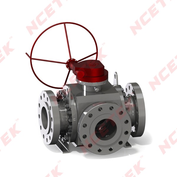
Ball support method is a separate question from entry design. A floating ball valve holds the ball in place through contact with the seats, with line pressure pushing the ball against the downstream seat to improve sealing. The ball is not mechanically anchored to the body; it floats within the seat assembly.
This design suits smaller sizes and moderate pressure ranges, where the force on the ball remains manageable through seat contact alone. It appears in a range of pipeline and process applications where compact construction and straightforward operation are priorities.
An API Floating Ball Valve follows this principle, built to recognized dimensional and testing practices. It can be constructed in either side entry or top entry form. The floating design and the entry design are separate decisions that address different requirements — one concerns how the ball is supported under pressure, the other concerns how the valve is assembled and serviced.
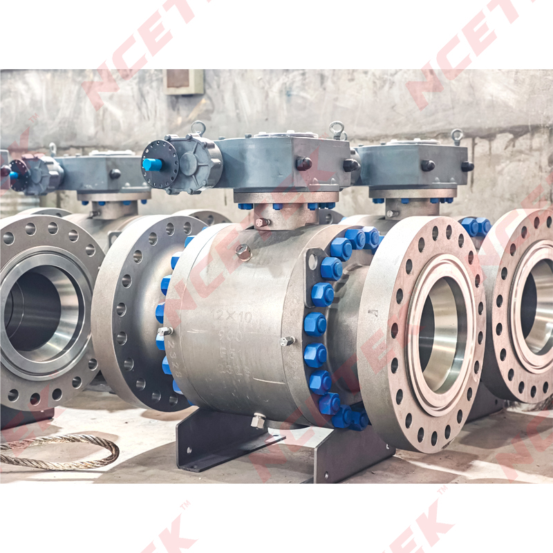
For higher pressure and larger sizes, a trunnion‑mounted design takes over. Here the ball is anchored at top and bottom, so line pressure does not push it against the seats. A Top Entry Trunnion Ball Valve combines that support method with the service access of top entry construction, which suits lines where both load handling and in‑place maintenance matter.
Service access separates them clearly. Top entry allows internal work with the valve in place. Side entry typically requires removal, which means the line must be opened and the valve transported for service.
Body construction follows from that difference. A single‑piece body with a top opening has fewer joints through the pressure shell than a multi‑piece body joined along a vertical split. Fewer joints mean fewer potential leak paths, though each joint in either design must be properly assembled and tested.
Assembly proceeds differently. Top entry loads components from above; side entry loads them between body sections. Both methods are established and reliable when procedures are followed.
Piping requirements diverge. Top entry needs clearance above the valve for bonnet removal. Side entry needs space to separate body sections and, in many cases, to remove the valve from the line entirely. Which requirement is easier to satisfy depends on the installation.
Weight and footprint vary by size and pressure class rather than by configuration alone, though a single‑piece body may distribute material differently than a multi‑piece assembly.
Typical settings reflect these factors. Top entry appears where maintenance access is limited and downtime is costly — buried lines, welded sections, offshore or remote installations. Side entry appears where valves are accessible and can be taken out of service without disrupting other work.
Entry design is one consideration among several. A few others carry weight in the decision.
These factors interact. A welded valve in a remote location points toward top entry. An accessible flanged valve in a plant with a maintenance shop nearby may work well with side entry. Neither answer applies universally.
Both configurations isolate flow and both seal reliably when specified and maintained correctly. The difference lies in how they are assembled and how their internal parts are reached.
Top entry design moves service access to the top of the valve. The body remains connected, the pipeline stays in place, and internal components are reached through the bonnet. That arrangement suits lines where removal is impractical or downtime carries a cost.
Side entry construction follows a different assembly logic. It offers a well‑established path for accessible installations where a valve can be taken out of service when needed.
Ball support method is a separate matter. An API Floating Ball Valve suits smaller sizes and moderate pressure through seat contact, while a Top Entry Trunnion Ball Valve addresses higher loads with anchored support and in‑place service capability.
The practical path is to define the pipeline conditions first — size, pressure, connection type, access, and maintenance expectations — and let those conditions point toward the construction that fits. Matching the valve to the line tends to produce smoother operation than adapting the line to the valve.
 nce@cnnsv.com
 +86-15727968392 / +86-15397375798
 +86-577-67091815
 +86-577-67091815
 Dongou Industrial Zone, Oubei Street, Yongjia County, Wenzhou City, Zhejiang Province, China


Contact Us