
 русский
 简体中文
简体中文

Valve operation is closely connected with the way internal parts carry pressure and move against each other. When a ball valve opens or closes, the actuator has to overcome several forms of resistance. Friction between the ball and seats, pressure acting on the ball, sealing force, and the condition of the moving parts can all affect the required torque.
Floating and trunnion‑mounted ball valves handle these forces in different ways. A floating ball is not fixed to a stem and is able to shift slightly under pressure. A trunnion‑mounted ball, in contrast, is supported by fixed components that hold its position during operation. The difference may appear simple from the outside, yet it changes how the valve responds to pressure and how much rotational force is needed.
For manufacturers and equipment engineers, torque selection is therefore tied to valve construction rather than actuator size alone. Looking at the internal load path makes the difference between the two designs easier to understand.
Torque is the turning force needed to move the ball from one position to another. The amount required is not determined by the handle, stem, or actuator alone. Internal contact between parts can create resistance before the ball begins to rotate and while it moves through its operating range.
A ball valve normally has a spherical closure element positioned between two seats. When the ball turns, its surface moves against or close to the sealing surfaces. Pressure from the fluid can also change how firmly the ball is pressed toward a seat. As that contact force changes, so can the friction that the actuator has to overcome.
Several conditions can contribute to operating resistance:
Valve geometry determines how these forces are transferred. A floating design allows the ball to respond to pressure by moving slightly toward the downstream seat. That movement can increase contact at the sealing surface. A trunnion design uses fixed supports to carry the ball, changing the way pressure loads reach the seats and supporting parts.
The difference matters during both opening and closing. A valve may require a different amount of torque at different points in its movement because contact conditions are not necessarily constant. Starting movement can also behave differently from continued rotation.
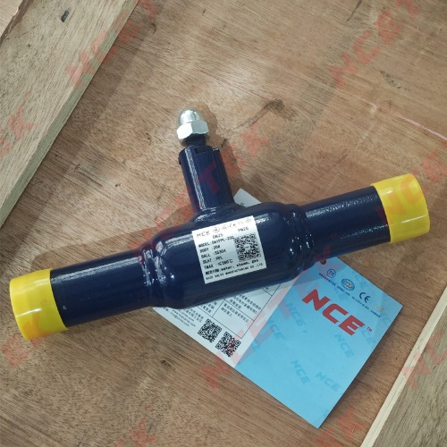
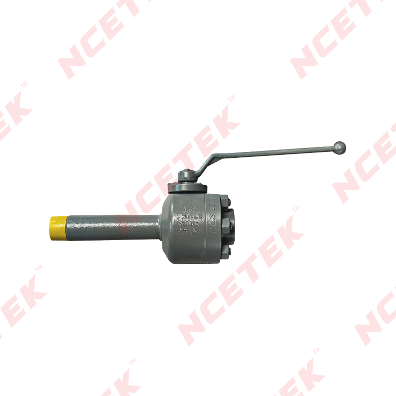
For a Fully Welded Floating Ball Valve, the welded body construction and floating ball arrangement have to work together. The body provides the pressure boundary, while the internal design determines how the ball, seats, and stem respond during operation. Torque selection needs to consider the complete arrangement rather than treating the valve body and operating mechanism as separate issues.
A floating ball valve gets its name from the way the ball is supported. The stem turns the ball, while the ball itself is allowed a limited amount of movement inside the valve body. When pressure enters the valve, the fluid force can push the ball toward the downstream seat.
That movement has an important effect on friction. The greater the contact between the ball and seat, the more resistance may be present when the stem tries to rotate the ball. The sealing arrangement is useful for maintaining a closed flow path, yet it also becomes part of the torque calculation.
During opening, the ball has to move away from its closed position while overcoming the forces holding it against the seat. During closing, the ball moves back toward the sealing position. Pressure conditions on either side can change the forces acting on the ball, so the torque behavior can vary with the operating condition.
The relationship can be viewed in a simple sequence:
Pressure condition → ball movement → seat contact → friction → required torque
The sequence is not identical in every valve because seat shape, surface condition, material selection, and internal clearances can all change the way the forces develop.
The stem also contributes to the overall resistance. If the stem seal is compressed more firmly, rotational resistance may increase. Surface finish and lubrication conditions can also influence movement. For this reason, measuring or estimating torque from the ball and seats alone can leave out other sources of resistance.
A floating arrangement can be useful where the valve structure allows pressure to assist the sealing action. At the same time, the resulting contact force needs to be considered when matching an actuator. A mismatch can make the actuator work harder than expected, particularly under operating conditions that increase ball‑to‑seat contact.
The construction of a Fully Welded Floating Ball Valve adds another consideration. Since the body is formed as a welded pressure‑containing structure, access to internal parts is handled differently from valves with a bolted body. The internal support and sealing arrangement still determine the operating behavior, so manufacturing control around these components remains closely connected with torque performance.
A trunnion‑mounted ball valve uses fixed supports to hold the ball in position. Instead of allowing the ball to move freely toward a downstream seat under pressure, the ball is supported by a lower and upper mounting arrangement. The stem turns the ball while the supports carry part of the mechanical load.
That changes the path through which pressure forces travel.
In a floating arrangement, pressure can push the ball toward a seat, increasing contact force. In a trunnion arrangement, the fixed supports carry much of the ball load, while the seats are arranged to maintain contact with the ball. Because the ball does not shift in the same way, the relationship between pressure and seat friction is different.
The result is not simply a question of one design needing more torque than the other in every situation. Actual torque depends on valve construction, sealing arrangement, pressure conditions, materials, and operating state. The useful distinction is how each structure manages the forces that create resistance.
| Structural Feature | Floating Ball Design | Trunnion Ball Design |
|---|---|---|
| Ball support | Ball can move slightly | Ball is held by fixed supports |
| Pressure response | Pressure can push the ball toward a seat | Supports carry ball loading |
| Seat contact | Influenced by ball movement | Managed through seat arrangement |
| Main friction areas | Ball, seats, stem, seals | Seats, stem, supports, seals |
| Torque behavior | Closely linked to ball‑to‑seat contact | Closely linked to support and sealing conditions |
For actuator selection, this difference becomes important because the torque path is part of the mechanical design. A valve with a fixed ball support system may distribute internal forces differently from a floating valve, even when both valves perform the same basic flow‑control function.
The operating condition also matters. Changes in pressure can alter seat loading, while changes in material condition can affect friction at contact points. Looking only at nominal valve size or external appearance does not provide enough information for a meaningful torque assessment.
That brings the discussion toward the factors that actually change the torque requirement between the two structures: support arrangement, sealing contact, pressure loading, and the materials used at moving surfaces.
Pressure changes the way forces act inside a ball valve, so it can also change the turning force required during operation. The effect depends on how the ball is supported and how the seats respond to pressure.
In a floating design, fluid pressure can move the ball slightly toward the downstream seat. Greater contact between the two surfaces can increase friction during rotation. The valve may therefore feel different under different pressure conditions even though its external structure remains unchanged.
A trunnion‑mounted design handles the same pressure in another way. Fixed supports hold the ball in position, allowing part of the pressure‑related load to pass through the support structure rather than through movement of the ball itself. Seat loading still matters, yet the force path is different from that of a floating ball.
Pressure direction also deserves attention. Conditions on the upstream and downstream sides can affect how the seats contact the ball. When pressure changes during operation, the load carried by individual internal parts may change as well. That can influence the torque required to start movement and the torque needed while the ball continues to turn.
For valve selection, several questions are useful:
A valve intended for a stable pressure environment may behave differently from one used where pressure varies frequently. The same applies to startup and shutdown. A valve that moves easily under one condition may show different resistance when pressure is applied on one side.
The relationship between pressure and torque is therefore structural rather than purely numerical. The internal support method, seat arrangement, and sealing surfaces all influence how pressure becomes mechanical resistance.
Materials used around the ball, seats, stem, and sealing areas have a direct connection with friction. Two valves with similar dimensions can have different operating behavior when their contact surfaces or sealing materials differ.
The ball needs to rotate smoothly while maintaining contact with the seats. A hard or rough surface can increase resistance, while changes in surface condition caused by wear, contamination, or improper handling can also affect movement. Seat material has a similar influence because it must provide sealing contact without creating unnecessary resistance during rotation.
Sealing force creates another part of the torque requirement. A tighter contact condition can support flow isolation, yet it may also increase the force required to turn the ball. Designers have to consider both functions together rather than treating sealing and operation as unrelated features.
Stem seals should also be included in the assessment. The stem transfers rotational movement from the actuator to the ball, so resistance around the stem becomes part of the total operating load. Poor surface condition, excessive compression, or contamination can make the stem harder to turn.
Material compatibility matters as well. The fluid passing through the valve can interact with internal materials, depending on the application. Temperature and operating conditions can influence how sealing materials behave, which may alter friction during use.
A practical material review can focus on:
For a Fully Welded Floating Ball Valve, these details remain important even though the welded body is a major part of the valve construction. The body and welds form the pressure‑containing structure, while the ball, seats, stem, and seals determine much of the movement inside that structure.
Torque should consequently be considered alongside sealing requirements, material selection, and operating conditions. Focusing on only one component can give an incomplete picture of how the valve will behave.
A welded valve body changes how the valve is constructed, yet it does not remove the need to assess internal operating resistance. With a floating ball arrangement, the ball can still respond to pressure, while the seats and stem remain closely connected with the torque requirement.
The actuator needs to match the actual mechanical behavior of the valve. A suitable match starts with the valve's operating condition rather than simply choosing an actuator based on external valve size.
The following areas usually need to be considered together:
A welded body can also influence installation considerations. Once the valve becomes part of a pipeline, surrounding pipe loads and installation conditions should not be ignored when evaluating operation. Mechanical stress or poor alignment can affect how internal components behave.
The key point is that actuator matching is a system‑level task. The valve structure establishes the basic torque behavior, while pressure, sealing, materials, installation, and service conditions can change the actual resistance.
This is particularly relevant when comparing a floating design with a trunnion design. Their external purpose may be similar, but their internal load paths are not. Treating them as mechanically interchangeable without checking the internal arrangement can result in an actuator selection that does not reflect the actual operating condition.
Actuator selection becomes easier when the valve's mechanical conditions are clearly identified beforehand. The starting point is the valve design itself, followed by the conditions under which it will operate.
A useful check can begin with the following points:
Operating frequency can also affect the decision. A valve that moves occasionally may have different practical requirements from one that cycles regularly. Repeated movement can gradually change contact surfaces, seals, and lubrication conditions, so the expected service pattern should be part of the assessment.
Maintenance conditions deserve attention as well. Internal contamination, residue around moving parts, or changes in sealing surfaces can increase resistance over time. Regular inspection can help identify changes before they affect normal operation.
The comparison between floating and trunnion designs is therefore better viewed through their force paths. A floating ball can shift under pressure and increase seat contact, while a trunnion‑mounted ball remains supported as pressure loads pass through its fixed mounting arrangement. Both designs still depend on the condition of their seats, stem, seals, materials, and surrounding installation.
For equipment engineers and valve manufacturers, torque selection works best when these factors are considered as one connected mechanical system. The valve's internal structure sets the foundation, while pressure, material condition, sealing contact, and operating requirements determine how that structure behaves in service.
 nce@cnnsv.com
 +86-15727968392 / +86-15397375798
 +86-577-67091815
 +86-577-67091815
 Dongou Industrial Zone, Oubei Street, Yongjia County, Wenzhou City, Zhejiang Province, China


Contact Us