
 русский
 简体中文
简体中文

Hydraulic equipment often looks simple from the outside, although fluid movement inside the system can involve several different routes and working conditions. A single machine may include multiple cylinders, actuators, or working sections that do not always require hydraulic fluid at the same time. In such situations, the pipeline layout needs a component that can help change or control the direction of fluid movement without rebuilding the entire connection structure.
A three-way valve is used for this type of situation. It connects three flow paths together, allowing hydraulic fluid to move between different sections according to the operating requirement. The valve does not create hydraulic power by itself; instead, it works as a control point inside the pipeline, deciding how fluid travels through the system.
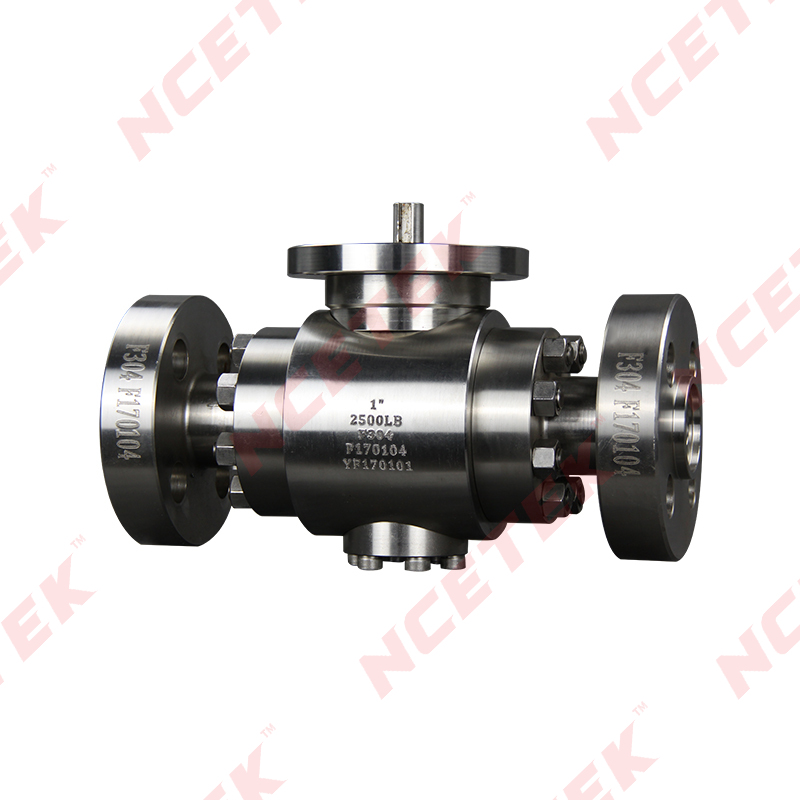
A High Pressure Three Way Valve is applied in hydraulic systems where the valve needs to work under higher pressure conditions while managing more than one flow route. The position of the valve is usually planned according to the equipment structure, pipeline direction, working sequence, and future maintenance needs.
A common example can be found in machinery with separate movement processes. One section may need fluid supply during a certain operation, while another section remains inactive. Changing the flow route through a three-way valve allows the system to support different actions without adding unnecessary pipeline branches.
Typical reasons for using a three-way valve include:
In practical engineering work, valve selection is rarely based on one condition alone. The pressure environment, fluid characteristics, installation location, and frequency of operation all influence whether a certain structure is suitable. A valve that matches the pipeline design can help reduce adjustment work during later operation.
Many hydraulic problems are related to the connection between components rather than one individual part. A pump, pipe, actuator, and valve all influence each other during operation. When a valve is placed in an unsuitable position or selected without considering the complete system, flow control may become harder to maintain.
A Three Way Ball Valve Manufacturer usually studies these application conditions during production because different hydraulic systems require different connection methods and structural designs. Understanding the working environment helps determine how the valve should be manufactured and applied.
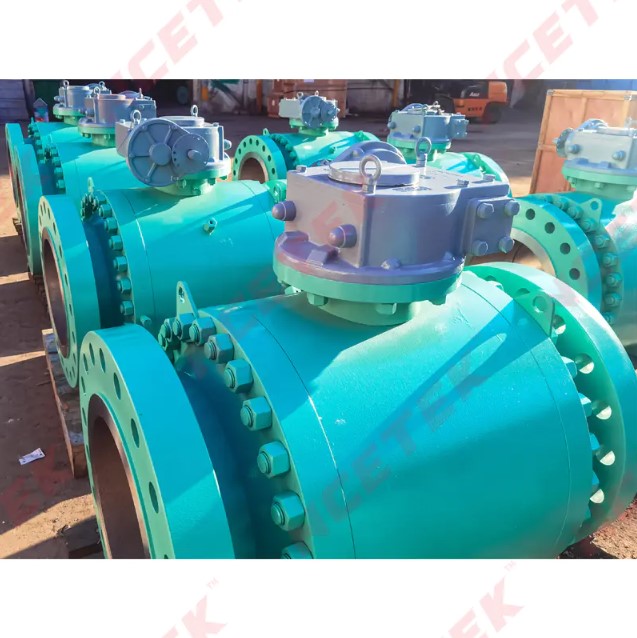
Inside a hydraulic system, fluid movement depends on the route created by connected passages. A three-way valve changes this route through its internal structure, allowing fluid to enter from one direction and leave through another according to the selected position.
The process appears straightforward, although several details affect actual performance. The internal passage needs to match the required flow direction, while sealing areas need to maintain stable contact during operation. A small change in internal structure can influence how smoothly fluid moves through the valve.
Pressure is an important consideration because hydraulic fluid transfers force through the system. When pressure conditions change, connection areas and sealing sections experience different working conditions. Valve structure needs to match these situations so that the flow path remains stable during normal use.
Several points are usually considered when evaluating valve operation:
For example, a valve placed close to an actuator may experience frequent flow changes because the actuator moves regularly during operation. Another valve installed in a service section may mainly support separation and inspection work. Although both valves control fluid movement, their working conditions are not exactly the same.
The relationship between the valve and other hydraulic parts also requires attention. Fluid does not stop at the valve; it continues through pipes and reaches different working components. Any change in flow direction can influence how other sections respond.
A suitable three-way valve arrangement is therefore connected with the entire hydraulic design. The valve needs to fit into the system instead of being considered as an isolated component.
Three-way valve structures are used in hydraulic systems where different flow paths need to be managed within a limited pipeline arrangement. The equipment type may vary, while the basic requirement remains similar: controlling where hydraulic fluid moves during different working conditions.
Industrial machinery often contains multiple hydraulic functions. A machine used for pressing may require different movement stages from a machine used for positioning or clamping. Each stage may need a different fluid route, making pipeline control an important part of system planning.
Common application situations include:
In a machine with several hydraulic actions, changing the fluid direction manually through pipe modification would create unnecessary work. A three-way valve provides a simpler way to organize existing routes and allows the system to respond to different operating requirements.
Maintenance is another practical reason for using this structure. During equipment inspection, one section may need to stop working while another section continues operating. A suitable valve arrangement can help separate specific routes and make maintenance planning easier.
Working conditions also affect valve application. Equipment used in manufacturing environments may experience vibration, dust, or frequent operation changes. Systems installed in cleaner areas may face different concerns. Because of this, the valve structure needs to match the actual environment where the hydraulic system operates.
Choosing a valve for a hydraulic system requires attention to the complete working process. Pipeline arrangement, equipment movement, maintenance requirements, and operating conditions are connected. A three-way valve becomes useful when its structure fits the way fluid needs to move inside the system.
A hydraulic valve usually makes sense only when it fits the working condition around it. Pressure level is one part, while pipe route, installation room, fluid condition, and service access all matter at the same time. A valve that looks suitable on paper may still need extra adjustment once it reaches the actual system, especially when surrounding pipes leave little room for movement.
Working pressure is often checked early, although pressure alone does not tell the full story. A valve in a busy hydraulic line may face repeated opening and route switching, while another valve in a service section may stay in one position for long periods. Those two situations place different demands on the same component, so selection usually follows the complete system layout rather than a single specification.
Pipeline direction is another point that changes the choice. Some hydraulic circuits need flow to move between two operating sections, while other layouts need one section to be separated during inspection. In both cases, the valve position must match the way the fluid path is arranged. Once the valve ports do not line up with the line direction, installation becomes slower and the risk of later correction increases.
Several practical details are often reviewed before installation:
Fluid condition also deserves attention. Different hydraulic fluids may behave differently around internal sealing areas, so material choice and internal construction need to fit the working medium as well as the pressure condition. A valve used in one hydraulic setup may not feel suitable in another, even when both systems appear similar from the outside.
Installation space often creates quiet problems that only show up during assembly. A valve placed close to walls, frames, or other parts may be difficult to turn into position, and a poor angle can make sealing work less steady. In field work, those small details often matter more than the initial selection sheet.
Valve structure affects how fluid enters, turns, and leaves the passage. In a hydraulic circuit, fluid movement is not only about switching on or off; it is also about keeping the route clear enough for the rest of the system to work in the right sequence. A three-way structure gives the system a way to connect, separate, or redirect flow without rebuilding the pipeline every time the working condition changes.
The internal passage arrangement plays a large part in that process. When the passage is shaped for a certain route, fluid can move through the valve in a predictable way. When the route changes, the valve position changes too, and the system responds by sending fluid to another section.
Sealing matters just as much as passage layout. Hydraulic fluid carries force, so any weakness around a sealing area may show up as a change in operation or a sign of wear during inspection. A valve body that matches the working pressure and the surrounding connection method usually stays easier to manage over time.
| Valve Structure Area | Practical Effect On System Use |
|---|---|
| Internal Passage | Guides fluid to the needed route |
| Sealing Section | Helps keep movement controlled |
| Connection Area | Affects installation and alignment |
| Operating Position | Changes how fluid is directed |
During operation, the valve works together with other hydraulic parts instead of acting alone. Pump output, pipeline route, and actuator movement all change how the valve behaves inside the circuit. That is why inspection often focuses on the whole section around the valve rather than on one part in isolation.
Minor changes in system behavior may point to a valve issue, though they may also come from nearby pipes or connection points. Careful checking usually starts from the visible route, then moves inward to the valve and sealing areas. That approach helps avoid replacing parts that are still working normally.
Valve production is tied closely to how the component will be used in the field. A Three Way Ball Valve Manufacturer does not only build a flow part; the manufacturer also needs to consider how the valve will fit with real hydraulic layouts, real maintenance habits, and real installation limits.
Different hydraulic systems ask for different construction details. Some require simple switching between routes, while others need a valve that can sit in a compact area without making later service difficult. Production choices need to reflect that variation, since one fixed structure does not suit every circuit.
Assembly accuracy matters during production because small differences can affect how smoothly the valve moves or how well the sealing area sits against the body. A valve that leaves the factory with stable dimensions and a clear internal route is easier to place into a working system.
Manufacturing attention often includes:
Communication between manufacturer and system planner also helps shape a better result. Information about pressure condition, layout space, and operating habits can guide production choices in a practical way. That kind of exchange is often more useful than broad product descriptions because the valve needs to solve a real installation problem.
Long-term use depends on routine checks, not only on the original installation. A valve may work well at the beginning, then slowly pick up wear or connection changes through regular operation. Inspection keeps those changes visible before they turn into larger work.
Maintenance around a three-way valve usually starts with the outer connection points. Loose fittings, dirt around the body, or changes in movement feel may indicate that the system needs attention. A clean surface also makes it easier to notice whether the valve has shifted, leaked, or become harder to operate.
Useful maintenance habits often include:
Operation habits also matter. Sudden pressure changes, poor alignment during installation, or repeated forcing of the valve can create extra stress on the system. Once the valve is treated as part of a larger hydraulic path, maintenance becomes easier to plan and less likely to disturb nearby sections.
A High Pressure Three Way Valve fits into a hydraulic system where flow routes need to shift without rebuilding the piping each time. Its use depends on pressure, layout, and service needs, while long-term reliability depends on installation care, routine inspection, and the way the whole circuit is managed.
 nce@cnnsv.com
 +86-15727968392 / +86-15397375798
 +86-577-67091815
 +86-577-67091815
 Dongou Industrial Zone, Oubei Street, Yongjia County, Wenzhou City, Zhejiang Province, China


Contact Us