
 русский
 简体中文

In industrial automation, a valve and its actuator operate as one coordinated unit. The valve controls fluid flow, and the actuator supplies the movement that opens, closes, or adjusts it. When the system runs at elevated temperatures, selection takes more than confirming that the connection points fit together.
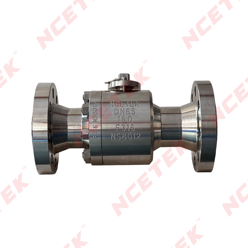
A High Temperature Ball Valve may serve process lines, heating systems, and thermal equipment where hot fluids or heated surroundings affect operation. Its internal parts and external connections must suit the service conditions. The actuator must also deliver the required movement without being compromised by heat from the valve, nearby pipes, or surrounding equipment.
A Heat Resistant Ball Valve addresses the thermal needs of the valve itself. Torque, actuator type, control signals, mounting, temperature exposure, and maintenance access all shape the final configuration, so engineers and purchasing teams should evaluate the valve and actuator as one operating assembly.
A ball valve turns a drilled ball to control flow, and the actuator rotates the stem to move that ball between its positions. If the actuator cannot supply the required movement, the assembly may not reach full travel. A valve with high operating resistance can also place unnecessary demand on the actuator, which shows up as irregular motion or accelerated wear.
Heat adds another layer. It changes the dimensions, sealing behavior, and movement of valve components. It can also reach actuator seals, lubricants, electrical parts, and mounting materials through the stem, bracket, and pipework. An actuator can warm up noticeably without ever touching the process fluid.
| Selection Area | What Engineers Consider |
|---|---|
| Valve function | Isolation or flow adjustment |
| Operating torque | Effort needed under service conditions |
| Actuator type | Suitability for the movement and control method |
| Temperature exposure | Heat around the valve, actuator, and nearby equipment |
| Control interface | How commands are received and position is reported |
| Installation layout | Mounting space, connections, and service access |
These factors should be reviewed before individual components are purchased. Replacing an actuator after assembly often means reworking brackets, wiring, or control programming, and those changes cost time on site.
Torque is the turning effort needed to move the stem. It is rarely constant through the travel. Resistance can differ when the ball begins to move, midway through the stroke, and as it seats at the end. Temperature, pressure, seat contact, deposits, and the condition of moving parts all influence it.
The valve manufacturer's operating information is the reference point. The duty also matters. A valve that sits in one position for weeks places different demands on an actuator from one that changes position every few minutes during a batch process. A valve that turns easily on a workbench can feel noticeably different once it is hot and pressurized.
Several questions help structure the review:
More force does not solve every operating problem. Excess force stresses the stem, travel stops, and seals, and it can hide a developing fault such as contamination or misalignment. The sound approach is to match actuator capability to documented valve requirements while allowing for the conditions expected in service.
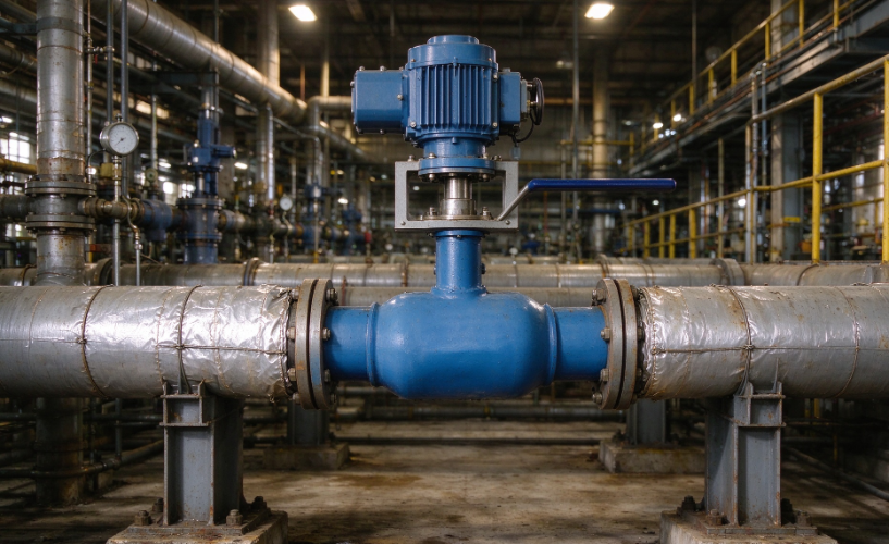
Electric actuators use a motor and suit equipment that works with electrical command signals and position feedback. Pneumatic actuators use compressed air, which fits plants that already have a compressed air supply, such as packaging or food processing lines. Hydraulic actuators use pressurized fluid and make sense where a hydraulic system is already installed and maintained.
| Actuator Type | Main Selection Considerations |
|---|---|
| Electric | Power supply, control signals, position feedback, environmental protection |
| Pneumatic | Air supply, control arrangement, response needs, seal suitability |
| Hydraulic | Fluid supply, lines, connection integrity, service access |
The decision should reflect available utilities and the complete application rather than habit. The actuator's own rated operating environment deserves particular attention. A valve may handle a hot fluid while the actuator sits beside a furnace wall or an uninsulated pipe, and the actuator must tolerate that location regardless of how the valve performs.
Heat moves through the stem, extension, bracket, pipework, and supporting steel. Seals may suit a narrower temperature range than the valve body. Lubricants can thicken or thin, cables and connectors may need specific protection, and mounting parts can shift slightly as they expand, which affects alignment.
Mapping likely heat paths during design avoids surprises. Review the stem, any extension, mounting parts, nearby pipes, insulation, and enclosures. Confirm the actuator's permitted environment, then check seals, cables, and lubricants against the expected exposure.
Any spacing or shielding must preserve stem movement, mounting strength, and access for inspection. Insulation that blocks a service point creates a different problem later. A Heat Resistant Ball Valve does not prove that the complete assembly tolerates the same conditions, because valve and actuator may have different limits.
A valve used for isolation needs reliable travel to open and closed positions, with clear confirmation that the movement finished. Repeated cycling raises questions about actuator duty and mechanical wear. Unstable signals can also trigger needless movement, and the cause then sits in the control logic rather than the hardware.
Flow adjustment needs additional care. A ball valve designed mainly for shutoff may not suit every form of continuous control, so valve design, actuator, and control method must match the intended duty.
| Control Requirement | Configuration Consideration |
|---|---|
| Open-and-close operation | Reliable travel to the required positions |
| Frequent cycling | Actuator duty and repeated movement |
| Flow adjustment | Valve suitability for the control function |
| Remote operation | Compatible command signals and feedback |
| Automated sequence | Coordination with sensors and controllers |
| Safe shutdown | Defined response under relevant system conditions |
Agreeing on the control method during design prevents rework. Late changes ripple into wiring, programming, and commissioning.
The valve is one part of a larger machine or process line. The actuator may exchange signals with a programmable controller, remote input and output devices, safety equipment, or a monitoring platform. Success depends on physical fit and coordinated control behavior.
Begin with the mounting interface. The actuator must connect securely to the stem, and the parts must suit the expected loads without side loading or misalignment. Then check space. Wiring, air or hydraulic lines, adjustment, and removal all need room, and nearby cable trays, guards, and supports often block access when they are overlooked.
A clear sequence keeps the review organized:
Testing parts separately shows that each one runs, but it does not show how they behave once connected. The assembled unit should be tested under conditions relevant to its intended use, following manufacturer instructions and project acceptance requirements.
| Test Area | What It Confirms |
|---|---|
| Mechanical movement | The actuator moves the valve through its intended travel |
| Position confirmation | Required positions are reached |
| Control response | Commands are received and handled as intended |
| Sealing checks | Applicable leakage requirements are met |
| Thermal suitability | The assembly suits the evaluated temperature conditions |
| Connection inspection | Mounting, wiring, and utility connections are secure |
| Feedback operation | Position information reaches the control system |
For automated lines, include the operating sequence. A valve may move correctly during an isolated check yet behave differently when its commands depend on other equipment. Results apply only to the conditions actually tested, so record those conditions clearly.
If the assembly falls short, identify the cause before adjusting anything. Torque demand, actuator settings, alignment, control signals, or process conditions may be responsible. Reviewing them together prevents a local adjustment from creating a new fault elsewhere.
A product description rarely shows whether a valve and actuator will work together on a given site. The specification should state process duty, temperature conditions, fluid compatibility, connection requirements, and control function. It should also cover the actuator's energy source, feedback needs, mounting arrangement, and environmental exposure. Stem extensions, protective arrangements, and control accessories belong in the same review.
Useful supplier questions include:
Clear answers before delivery show who is responsible for mechanical fit, control compatibility, and operating suitability. Early coordination among design, purchasing, and maintenance teams helps the chosen High Temperature Ball Valve assembly fit both the process requirements and the practical conditions of the installation.
 nce@cnnsv.com
 +86-15727968392 / +86-15397375798
 +86-577-67091815
 +86-577-67091815
 Dongou Industrial Zone, Oubei Street, Yongjia County, Wenzhou City, Zhejiang Province, China


Contact Us