
 русский
 简体中文

A maintenance crew arrives to replace a failed valve on a heated storage tank. The new valve has the right nominal size printed on the box. It will not thread onto the outlet, and the flange bolts sit in the wrong places. Half a day goes to hunting for adapters, and the tank stays out of service while everyone waits.
Stories like this are common, and they usually trace back to the same cause. Someone matched a pipe size and assumed the rest would follow. Choosing a Heat Resistant Ball Valve for a tank means checking the connection, the temperature, the pressure, the sealing materials, and the room around the installation, all together.
Searches often mix up a float valve and a floating ball valve, yet they do different jobs.
A float valve, sometimes called a ball float valve, uses a buoyant ball on an arm. As the liquid level rises or falls, the float moves and opens or closes the inlet. You see it in automatic tank filling and level control.
A floating ball valve is an on-off valve. A ball with a bore through the center turns to line up with the pipe or turn away from it. Under pressure, the ball shifts slightly toward the downstream seat to seal. A Heat Resistant Ball Valve in this family isolates or controls flow in lines where temperature calls for carefully chosen materials.
Getting this distinction right at the beginning avoids ordering a level-control device when what you need is an isolation valve, or the other way around.
Before looking at any valve, look at the tank outlet. The connection decides what can go on it, and checking it early saves adapters and awkward modifications.
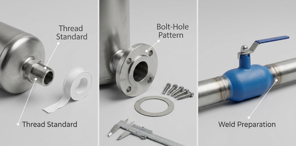
Threaded outlets. Small tanks and compact systems often use threaded connections, and two standards come up constantly, NPT and BSP. They look similar and are not interchangeable. NPT threads are tapered, while BSP comes in parallel and tapered forms and seals in different ways. A matching nominal diameter does not guarantee that two threaded parts will fit. Check the drawing or identify the existing fitting before ordering, and never force threads together. Damaged threads create leak paths that are difficult to fix.
Flanged outlets. Larger sizes and equipment that needs regular maintenance often use flanges. Matching diameter is only the start. The flange pressure class, facing type, bolt-hole pattern, gasket material, and available clearance all have to agree with the mating flange. Gaskets need particular care in heated service, because a general-purpose gasket can harden, creep, or fail when the temperature is outside its intended range. Follow the equipment specification instead of guessing.
Welded and adapted connections. Some systems use welded ends for a permanent arrangement, which can suit a valve whose material and design are intended for it. Adapters are sometimes the only way to join a valve to an existing outlet, but every adapter adds joints and possible leak points. Verify the adapter's material, pressure rating, temperature suitability, and connection standard before relying on it.
Nominal size is a label, not a measurement of the actual opening. Check the real dimensions of the tank outlet, the connecting pipe, and the valve ports against the technical drawings. A valve can carry the right label and still fail to fit.
A sensible sequence helps. Identify the outlet size and standard. Confirm the valve's inlet and outlet specifications. Check the internal passage. Compare the valve body with the available space. Decide whether an adapter is needed. Doing this on paper costs very little compared with doing it on site.
Port size deserves attention as well. A full-port valve has a passage close to the pipe's internal diameter, so it restricts flow very little. A reduced-port valve has a smaller opening through the ball, which can be fine when the system allows it. A larger valve is not automatically a better one. Choose the port that matches the flow the process needs and the equipment connected to it.
Walk around the installation too. Tank walls, supports, insulation, and neighboring equipment can block access. Make sure there is space for the handle or actuator to swing, for tools to reach bolts and threaded joints, for insulation around heated pipe, and for someone to get at the valve later to inspect seats and seals. Automated installations also need room for the actuator and enough torque capacity.
Temperature changes everything about how a valve behaves. The body, ball, seats, and stem expand at different rates, which alters the clearances between sealing surfaces. Non-metallic seats can soften or degrade. Packing can relax and lose compression. Exposed metal can oxidize, and friction can rise as parts change dimension. Repeated heating and cooling makes all of this worse.
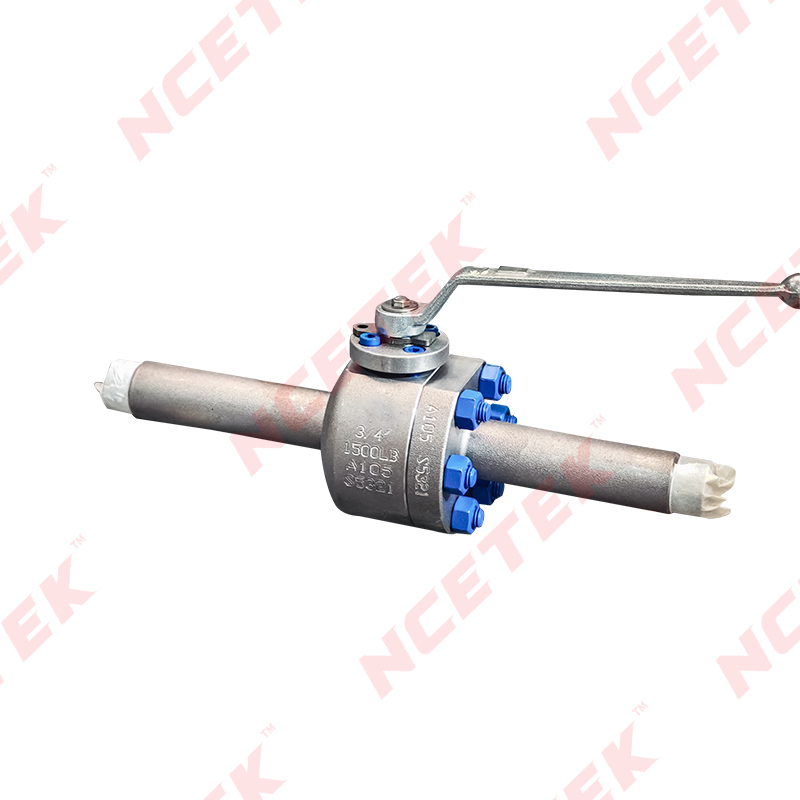
A Heat Resistant Ball Valve is built to cope with these conditions through suitable body materials, seat designs, and stem sealing. Depending on the design, it may use metal seats, graphite-based packing, heat-tolerant sealing materials, or treated internal surfaces.
The words heat resistant do not describe one universal capability. The usable range depends on the whole assembly, including the body, seat, packing, stem, and end connections, and the weakest part sets the limit. Read the manufacturer's pressure and temperature rating, and compare it with your actual service conditions, including temperature swings during start-up and shutdown.
Pressure and temperature must be read together. A valve's allowable working pressure usually falls as temperature rises, so a rating given at room temperature can give the wrong picture. Consider normal operating pressure, the upper limit the system might reach, design temperature, pressure surges, the fluid's characteristics, and heating cycles.
One hazard deserves special mention in systems carrying thermal oil or other heated liquids. When a ball valve closes, liquid can stay trapped in the cavity around the ball. As that liquid warms, it expands, and the pressure inside the cavity can climb sharply. The valve design or the system arrangement should include a suitable way to relieve that pressure where the service requires it.
Picking a heat-tolerant body and ignoring the seats and packing leaves the assembly with a weak link. The body, seat, and seals have to suit the fluid, the temperature, the pressure, and the surroundings together.
Stainless steel is widely used where corrosion resistance matters. Carbon steel can be suitable where the process allows its mechanical and corrosion behavior. Other alloys come into play for particular chemical or thermal needs. Fluid composition, corrosion exposure, thermal stress, and the pressure and temperature rating all guide the choice.
Seats form the sealing interface between ball and body, and each material behaves differently. PTFE offers chemical resistance and low friction, yet its approved temperature range must be checked. Reinforced PTFE changes its mechanical behavior and still needs verification against the process. PEEK is valued for strength and thermal capability, though the grade and manufacturer rating matter. Graphite suits various elevated-temperature seals, with oxidation and media compatibility to evaluate. Metal seats serve demanding services and need a suitable surface finish and careful matching. A material name alone cannot prove suitability, so the complete assembly has to be reviewed under real conditions.
Stem packing deserves the same care. It keeps fluid from escaping around the stem, and in heated service it has to keep sealing through temperature changes and repeated operation. Check the packing material, how compression is applied, the stem finish, and what maintenance it will need.
A methodical approach prevents many connection errors and eases future maintenance.
Record the tank outlet details, including nominal size, thread standard or flange configuration, material, and pressure requirement, using equipment drawings or manufacturer documents whenever they exist. Then confirm the valve's configuration, covering body material, port size, end connection, seat material, packing, and operating limits. For a Heat Resistant Ball Valve, make sure the whole assembly is approved for the intended temperature and pressure.
Next, check alignment. The valve and pipe should come together without forcing them into position, because mechanical stress damages joints and sealing surfaces. Choose gaskets, thread sealants, and packing according to the connection design and process conditions, and avoid general-purpose products unless their temperature and chemical compatibility is confirmed. Finally, follow the manufacturer's instructions to inspect and test. Check the joints, operate the valve, and look for leakage under the approved test conditions before returning the equipment to service.
A good supplier explains how a valve configuration fits your installation instead of pointing to a product name. Come prepared with the information they need: the tank connection size and standard, working temperature, operating pressure, fluid medium, flow requirement, and a description of the installation environment, including space and maintenance limits. With these details in hand, a supplier can review the application and recommend something suitable.
A clear technical conversation before the order surfaces connection differences, material questions, and installation concerns while they are still cheap to fix. That conversation is usually the difference between a valve that goes on smoothly and one that sits in a corner of the workshop while the crew hunts for adapters.
 nce@cnnsv.com
 +86-15727968392 / +86-15397375798
 +86-577-67091815
 +86-577-67091815
 Dongou Industrial Zone, Oubei Street, Yongjia County, Wenzhou City, Zhejiang Province, China


Contact Us